Calibration — ComMarker B4 60W MOPA
Galvo geometry calibration for MeerK40t 0.9.8100 (JCZ / BJJCZ board, 110 mm lens) and the MOPA colour calibration tool. Updated 2026-10-31. Status: kit ready; sheet 1 not burned yet, so there are no measured results yet.
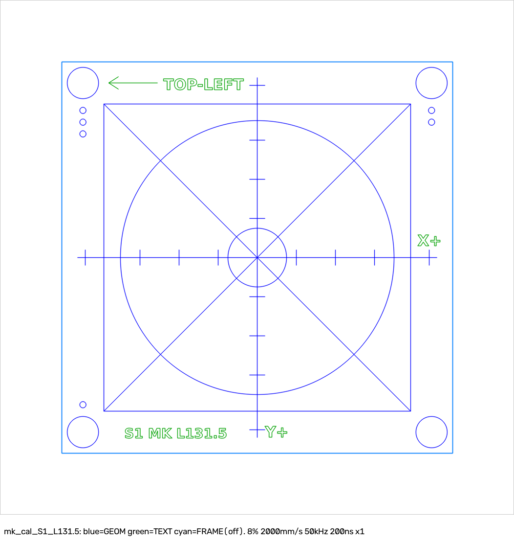
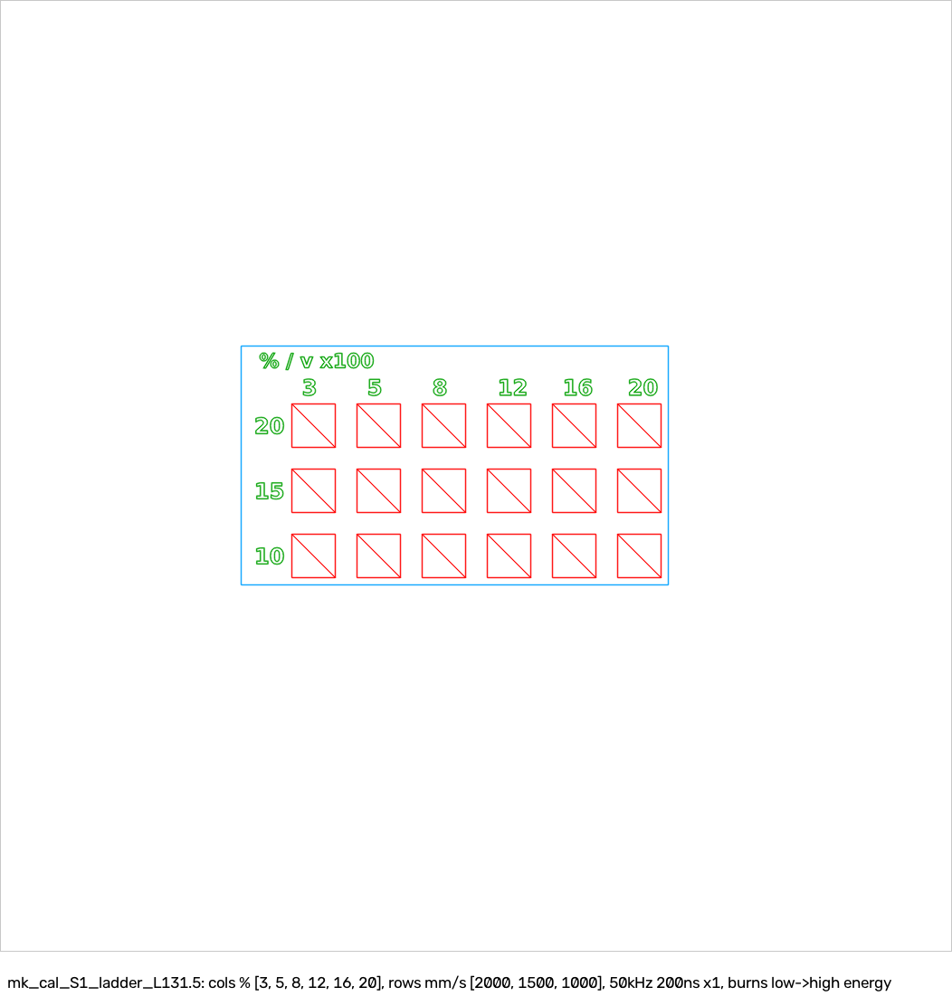
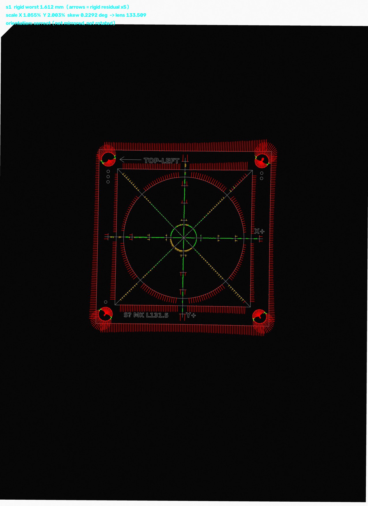
MeerK40t galvo calibration on black construction paper
Folder: /home/hank/laser/projects_shared/calibration_meerk40t/ · prepared 2026-10-31 · MeerK40t 0.9.8100 · JCZ/BJJCZ board (USB 9588:9899) · 110 mm lens (F-theta)
Safety rule: these files only prepare jobs. Hank presses Start himself. Nothing here starts a burn, framing or the red dot. Never launch MeerK40t with -a, because it auto-starts the laser.
What this calibrates
MeerK40t has never been calibrated on this machine. Three sheets of 8.5×11 in black construction paper are used:
| Sheet | Burn | Purpose |
|---|---|---|
| S1 | power ladder (mk_cal_S1_ladder_L131.5.svg), then the target (mk_cal_S1_L131.5.svg) |
choose a clean line setting; baseline distortion at the current settings (lens 131.5, stock jcz110.cor) |
| S2 | mk_cal_S2_L131.5.svg, using the new lens size + new .cor from the S1 analysis |
apply the correction; measure how the board responded (gamma) |
| S3 | mk_cal_S3_L131.5.svg, using the S2 result |
verify, or apply a fine-tune |
Target: worst point within the 100 mm square ≤ 0.2 mm, which matches LightBurn round 6 (0.186 mm).
Files
| File | What |
|---|---|
jobs/mk_cal_S1_ladder_L131.5.svg |
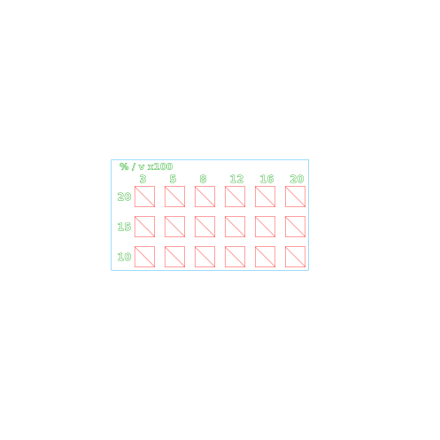
MeerK40t project. 18 cells: 6 powers (3/5/8/12/16/20 %) × 3 speeds (2000/1500/1000 mm/s), 50 kHz, 200 ns, 1 pass. Each cell is a 6 mm square plus a diagonal. The ops are ordered from lowest to highest energy. Labels burn at 8 %/2000. The FRAME op is output off. |
jobs/mk_cal_S{1,2,3}_L131.5.svg |
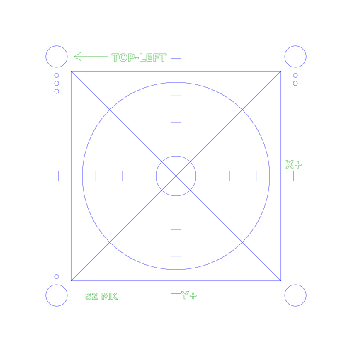
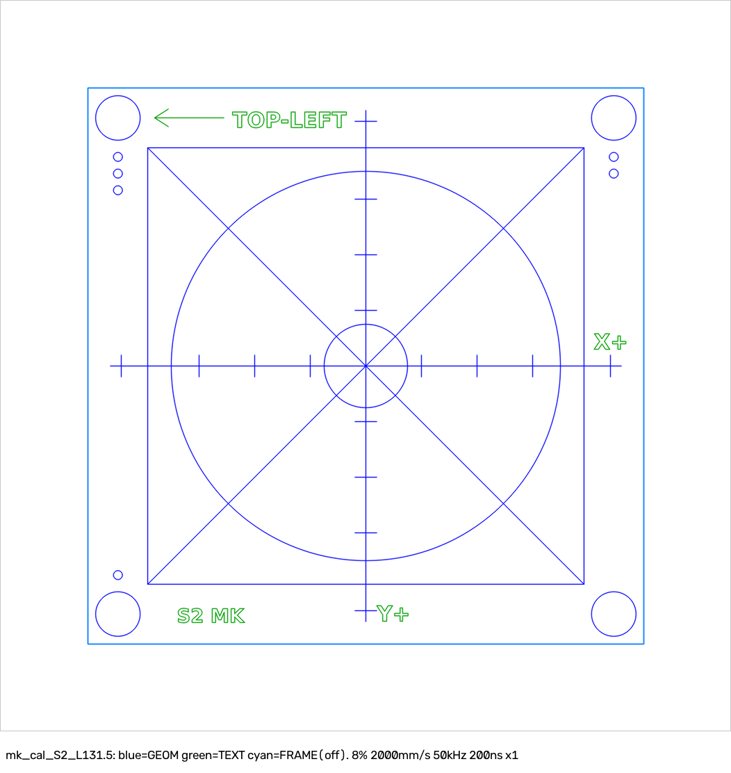
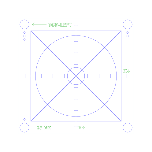
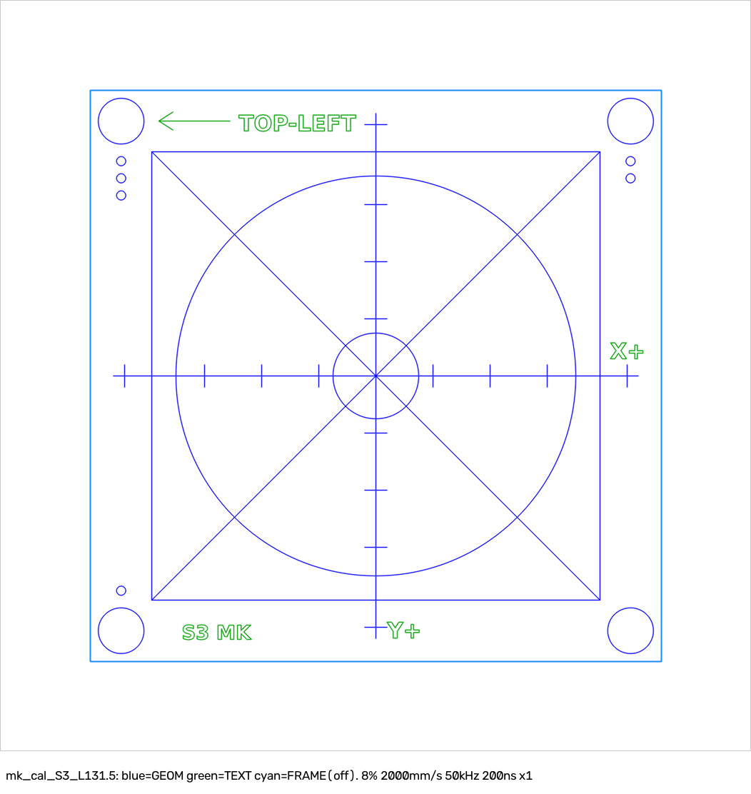
MeerK40t project for the 100 mm target. Ops: 1 GEOM (lines), 2 TEXT (outline labels), 3 FRAME (100 mm reference, output off). Default 8 %, 2000 mm/s, 50 kHz, 200 ns, ×1. |
jobs/*_plain.svg, *_preview.png |
the same geometry as plain SVG, and a picture of it |
jobs/jobs_L131.5.json |
every op setting in machine-readable form |
mk_cal_analyze.py |
analyses a 600 dpi scan and writes the report, overlay, new lens size, new flags and a corrected .cor |
mk_cal_design.py, mk_view_table.py |
shared geometry, and the MeerK40t view-flag matrices (generated from MeerK40t's own View class) |
gen_mk_cal.py |
regenerates the jobs (--lens --power --speed --freq --pw). Needs matplotlib, so run it on the box, not in the laptop venv. |
mk_cal_synth.py, selftest.sh |
synthetic burn/scan simulator plus an end-to-end self test |
selftest/ |
box self-test evidence (reports + JSON) |
ref/jcz110.cor |
read-only copy of the stock table, used for tests |
scans/ |
put the scans here (sheet1_scan_600.png …) |
results/ |
the analysis writes here |
PROPOSED_CONFIG.md |
the settings that will change, and how to change them safely |
Target geometry (mm, centred on the field, y down): outer square 100. Inner square 78.49 with both diagonals. Axis rulers ±46 with ticks at ±10/20/30/44. Circles: Ø70, Ø15, and four Ø8 corner circles at (±44.6, ±44.6). Orientation pips by the corner circles count 3 (top-left), 2 (top-right), 1 (bottom-left) and 0 (bottom-right). Text: "TOP-LEFT" with an arrow, "X+", "Y+", and the sheet label. The pips let the analysis detect a mirrored or rotated burn even without the paper snip.
Lens size: why 131.5 and not 110
- In MeerK40t,
Lens Size(Device settings → General → Width) is the only global scale control. Its scale is galvo ticks/mm = 65535 / lens_size, so the burned size is proportional to 1 / lens_size. - The physical lens is 110 mm, but the stock
jcz110.corand this galvo give about 498 ticks/mm at the centre, which LightBurn round 6 measured. 65536 / 498 ≈ 131.6 mm. That is why the config already sayslens_size = 131.5mm. - Typing 110 would make every burn about 19.6 % too big. So S1 runs at the current 131.5, and the analysis computes the exact value: new = old × measured / nominal.
- Gotcha: when you select a .cor file in the GUI, MeerK40t resets Width to 65536 / (cor header scale), which is 125.002 for jcz110-type files. After selecting a .cor, always type the lens size back in.
- There is an alternative table, Claude's
jcz110_r6_meerk40t.corwith lens 125.001, built from the LightBurn round-6 model. It has not been tested in MeerK40t. Keep it as a fallback only. Do not mix it with the S1 → S2 chain.
MeerK40t 0.9.8100 knobs (Balor/JCZ device)
| Knob | GUI location | Current | What it does |
|---|---|---|---|
| Lens Size | Device settings → General → Width | 131.5 mm | Global scale for both axes. It cannot fix X and Y separately. |
| Correction file | General → Correction File → Enable + File | on, /home/hank/laser/meerk40t/jcz110.cor |
A 65×65 table that the board applies. It is the only way to fix per-axis scale, skew, trapezoid, barrel/pincushion and off-centre error. |
| Flip X / Flip Y / Swap XY | Parameters → Axis corrections | F / T / T | Mirrors or rotates the design-to-galvo mapping. These are right if the burn reads correctly (TOP-LEFT at the back-left, text not mirrored). |
| Rotate View | Parameters → Axis corrections | 0 | Further 90° steps |
| Laserspot, Margins, redlight offsets | General / Red Dot | – | Do not affect burn geometry (the redlight offset affects the red dot only) |
| Correction tab (Device window) | – | – | A stub in 0.9.8100 that does nothing. Use a .cor file instead. |
These are the settings the analysis prints and writes into new .cor files. Format: JCZ_COR_2_1, 65×65 signed int32 (dx, dy), step 1024 ticks. How the board applies the table (sign) is checked by the gamma test on sheet 2. New tables are clamped to |v| < 32768.
Before you start (once)
- Snip about 8 mm off one corner of each sheet with scissors, at 45°. That corner is the "back-left" reference, so the analysis knows how the paper sat.
- Put a flat non-flammable backing under the paper: aluminium sheet, steel plate or a ceramic tile. Tape all 4 edges flat with masking tape. Paper must lie flat, because a wave in the paper is a focus and scale error.
- Focus the head on the paper surface the usual way (focus gauge / measured height for the 110 mm lens).
- Load files with File → Open in the running MeerK40t. Do not use
stand_center.bat, because it shifts everything by 38.25/23.25 mm. Do not usecal_run.bat, because it contains spool commands. After opening, press Ctrl+A then Ctrl+Shift+C to centre on the bed. The files are already centred at 65.75 mm for lens 131.5. Do this every time the lens size has changed.
Fire safety (every burn)
- Fume extraction on, enclosure or shield as usual, laser safety glasses on.
- Never leave a paper burn unattended. Stay at the machine with a hand on Stop / E-stop.
- Keep a wet cloth or a small extinguisher within reach. Black paper can glow or smoulder after a pass. Watch for 30 s after the job ends, then check for embers before you pull the paper.
- If there is any flame, any spreading glow, or a cell that ignites: hit Stop, and smother it with the wet cloth. Never blow on it.
- Only Hank presses Start. Framing or the red dot is Hank's choice. The files do not trigger them.
Sheet 1, step by step
- Prepare sheet 1 (snip at the back-left, tape it flat on the non-flammable backing). Slide it so its back third is under the centre of the lens. The ladder is about 66 × 37 mm.
- In MeerK40t: File → Open
jobs/mk_cal_S1_ladder_L131.5.svg→ Ctrl+A → Ctrl+Shift+C. Check the op list: 18 red ops01 … 18(low to high energy),99 LABELS, and aFRAMEop with output off. Device settings must be unchanged: Width 131.5 mm, jcz110.cor enabled, Flip X F, Flip Y T, Swap XY T, Rotate 0. - Hank presses Start and watches the ladder burn. If a cell flames, stop. The settings after it are hotter.
- Let it cool, then look at the ladder. The rows are speed (top 2000, middle 1500, bottom 1000 mm/s) and the columns are power (3/5/8/12/16/20 %). Pick the lowest-energy cell whose square and diagonal are continuous, crisp and clearly lighter or darker than the paper, without burn-through, charring or flame. That is the line setting. Rule from the laser lessons: stay at ≤12 % if a cell there is clean.
- Open
jobs/mk_cal_S1_L131.5.svg(Ctrl+A, Ctrl+Shift+C). Double-click op1 GEOMand op2 TEXTand set the chosen power and speed (keep 50 kHz, 200 ns, 1 pass).3 FRAMEstays output off. - Untape and slide the paper without rotating it (snip still at the back-left) so a clean area at least 110 mm square is centred under the lens and is clear of the ladder. Tape it flat again.
- Hank presses Start. The target takes well under a minute. Watch it, then let it cool and check for embers.
- Scan (next section) and run the analysis.
Scan (HP PhotoSmart 2600 on the laptop's USB)
Place the sheet face down, with the snipped corner fully on the glass (portrait, against the top-left of the glass). Then run on the laptop:
pkill -x scanimage; mkdir -p /home/hank/laser/projects_shared/calibration_meerk40t/scans && nohup scanimage -d 'hpaio:/usb/Photosmart_2600_series?serial=YOUR_SERIAL' --mode Color --resolution 600 --compression None -x 215.9 -y 297 --format=png -o /home/hank/laser/projects_shared/calibration_meerk40t/scans/sheet1_scan_600.png > /tmp/scan.log 2>&1 < /dev/null &
For later sheets, change sheet1 to sheet2 / sheet3. A scan takes about 2.5 min and is about 53 MB. Check it with cat /tmp/scan.log; ls -la …/scans/. The scanner's measured scale is 600.0 dpi in X and 599.70 dpi in Y, and the analysis uses those values by default. A face-down flatbed scan is not mirrored.
Analysis
cd /home/hank/laser/projects_shared/calibration_meerk40t
PY=/home/hank/.venvs/mk40t/bin/python
# sheet 1 (baseline: lens 131.5 + stock cor)
$PY mk_cal_analyze.py scans/sheet1_scan_600.png --lens 131.5 --cor-in /home/hank/laser/meerk40t/jcz110.cor --tag sheet1 --out results
# sheet 2 (use the lens and cor that sheet 1 produced; --prev measures how the board responded)
$PY mk_cal_analyze.py scans/sheet2_scan_600.png --lens <S1 lens> --cor-in results/sheet1_corrected_L<S1 lens>.cor --prev results/sheet1_result.json --tag sheet2 --out results
# sheet 3: same pattern with sheet2 files
If the flags were changed after a sheet, add --flip-x 0/1 --flip-y 0/1 --swap-xy 0/1 --rotate 0..3 with the flags that were in use for that burn. The defaults are the current 0/1/1/0.
Each run takes a few seconds and writes to results/:
<tag>_REPORT.txtcovers:- orientation (mirrored/rotated?) and recommended flags
- scale X/Y/mean, plus rulers vs square edges
- skew, trapezoid, and side bow (barrel/pincushion)
- centre offset
- circle ovality
- ruler tick errors
- mark strength by region (a weak corner suggests a focus/tilt problem)
- fit RMS
- worst point (before and after the lens-only fix)
<tag>_corrected_L<lens>.corand<tag>_corrected_L<lens>_half.corare new tables at full and half strength<tag>_overlay.jpgshows the residual arrows ×5<tag>_result.jsonholds the data. It is the input for--prev.
Response check on sheet 2+: gamma ≈ 1 means the correction acted as predicted. If gamma < 0, the sign is inverted, and the script automatically writes a sign-flipped table. If gamma is near 0, the table was ignored or transposed, and no automatic .cor is written. Stop and check that the cor was enabled and the lens was re-typed.
Applying the sheet-1 result (before sheet 2)
See PROPOSED_CONFIG.md. In short:
- Back up the config.
- Device settings → Correction File → File → choose
results/sheet1_corrected_L<lens>.cor. Keep Enable ticked. - Type the new Width (lens size) from the report back in, because selecting the cor reset it to 125.002.
- Change Flip/Swap/Rotate only if the report says the burn was mirrored or rotated.
- Open
mk_cal_S2_L131.5.svgwith the same op power and speed as S1, then Ctrl+A, Ctrl+Shift+C.
If the S1 worst point was very large (> 3 mm) or the overlay looks wrong, use the _half.cor for S2.
Self test (no laser, no scanner)
./selftest.sh /home/hank/.venvs/mk40t/bin/python (the laptop venv has no matplotlib; the simulator then skips the text labels and prints harmless numpy/matplotlib import warnings) simulates a distorted machine, then runs a sheet-1 scan, the correction, a sheet-2 scan and the analysis. Box result (2026-10-31):
- sheet 1 worst point 1.61 mm. Lens 131.5 → 133.509.
- sheet 2 worst point 0.043 mm, gamma 1.04.
Earlier box tests also passed: a mirrored machine (the flags were detected), and a sign-inverted board (gamma −1.02, auto-flipped, sheet 3 at 0.061 mm).
Downloads
- PROPOSED_CONFIG.md (3 KB)
- README.md (13 KB)
- gen_mk_cal.py (10 KB)
- jobs_L131.5.json (7 KB)
- meerk40t_calibration_kit.zip (714 KB)
- mk_cal_S1_L131.5.svg (59 KB)
- mk_cal_S1_L131.5_plain.svg (40 KB)
- mk_cal_S1_L131.5_preview.png (127 KB)
- mk_cal_S1_ladder_L131.5.svg (44 KB)
- mk_cal_S1_ladder_L131.5_plain.svg (18 KB)
- mk_cal_S1_ladder_L131.5_preview.png (78 KB)
- mk_cal_S2_L131.5.svg (55 KB)
- mk_cal_S2_L131.5_plain.svg (38 KB)
- mk_cal_S2_L131.5_preview.png (123 KB)
- mk_cal_S3_L131.5.svg (55 KB)
- mk_cal_S3_L131.5_plain.svg (38 KB)
- mk_cal_S3_L131.5_preview.png (123 KB)
- mk_cal_analyze.py (33 KB)
- mk_cal_design.py (4 KB)
- mk_cal_synth.py (6 KB)
- mk_view_table.py (2 KB)
- selftest.sh (1 KB)
- selftest_s1_REPORT.txt (3 KB)
- selftest_s1_overlay.jpg (185 KB)
- selftest_s2_REPORT.txt (3 KB)

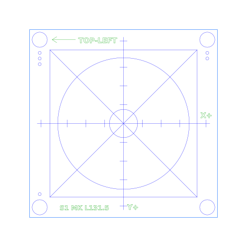



Measured results (scans, reports, final lens size and .cor) will be added here after sheets 1–3 are burned. The stock vendor table jcz110.cor is not redistributed.